
Note: I’m based in Korea, so some context here is Korea-specific.
When you start playing with Arduino, you realize that simply turning an LED on and off
brings a surprisingly primal sense of joy.
But… soon you realize that a single-color LED like the one above can only produce one color, and you start hunting for some kind of “LED that can produce any color”…
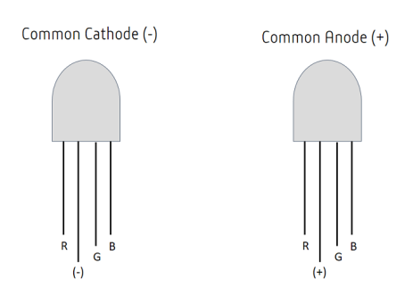
If you go on this adventure, you’ll come across Cathode (-) / Anode (+) LEDs like the one below.
And then if you look up wiring diagrams, you’ll find something roughly like this
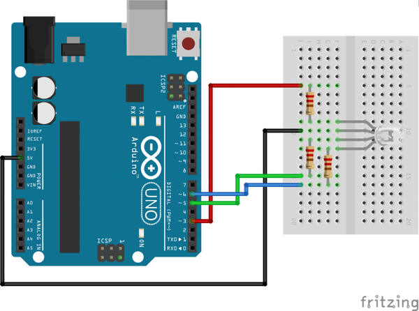
If you follow along and build it, hmm… it turns on and off nicely with the Arduino’s Digital Output.
But now? When you want to build something actually useful? Like wiring multiple LEDs in parallel? You start wondering how to do it. The circuit looks more complicated than a single-color LED…
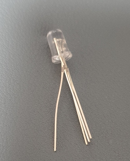
But actually, there’s nothing to it! The photo is of a 3-color Anode LED, but the Cathode version isn’t really any different (..)
Let’s figure out the principle.
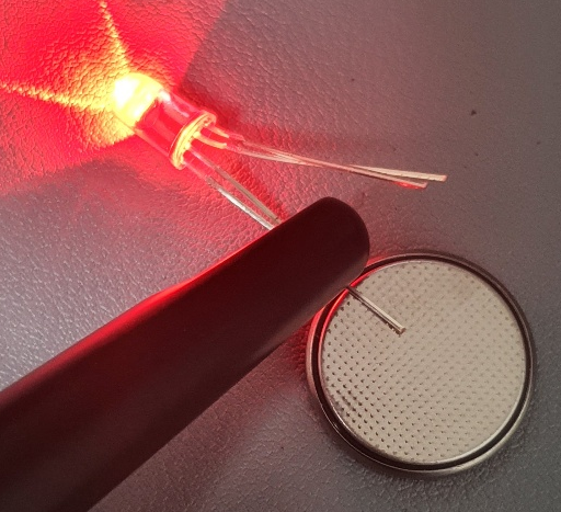
- Separate the LED’s RGB pins from the + pin (or - pin for a Cathode LED) like this.
- Then take a 3V button cell battery lying around, attach the + pin to the + side, and tap each RGB pin against the other side.
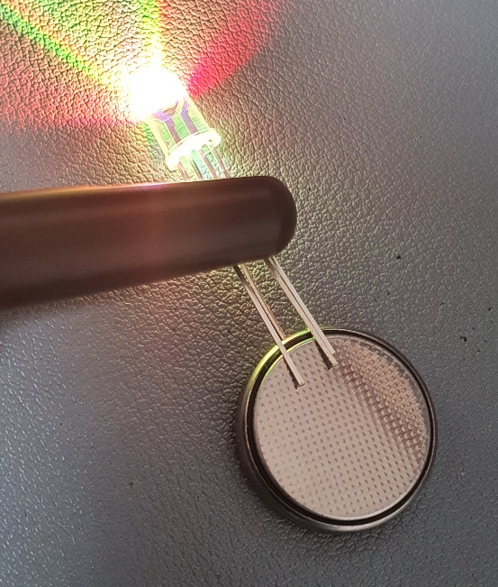
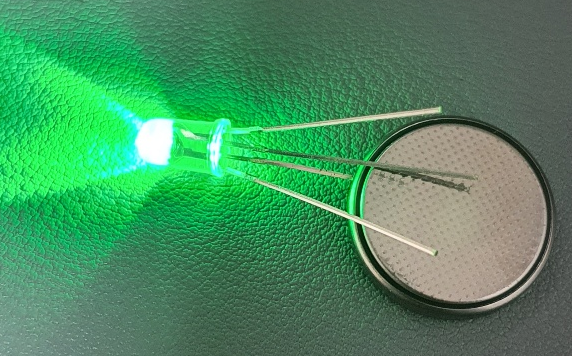
?? That’s right. A 3-color LED is actually just three single-color LEDs wired in parallel..
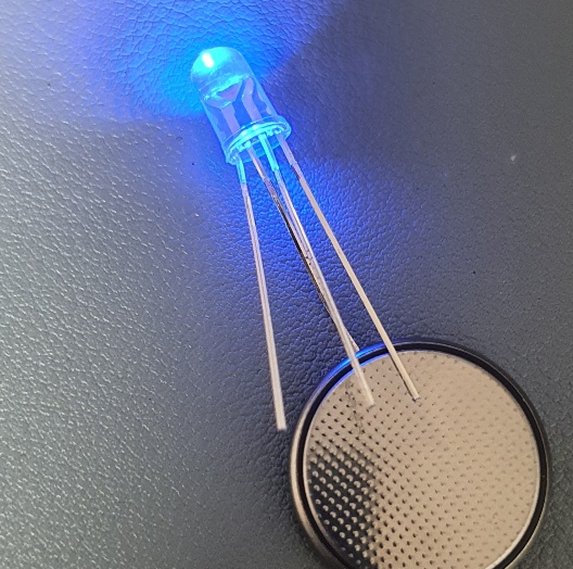
- So if you pull out one pin at a time, you can see that it works just like a single-color LED, regardless of the other pins (…)
Ah.. so once you know that a 3-color LED is just three single-color LEDs wired in parallel,
you remember that resistor stuff you did when wiring a single-color LED. Using three resistors apparently applies the appropriate voltage.
The Arduino circuit above also makes sense now. It was actually the same circuit as three single-color LEDs wired in parallel..
Ah.. I didn’t know this, so my 3-color LED sat in the storage closet for months.
Next time, I think I’ll just go for it and roll the dice, even if I have to fry one in the process..
Comments